Week 8: Embedded Programming
Wednesday 16/03/16: I was very happy to receive good comments from Emma, Luis and also from Neil as I got selected through the random generator. I felt encouraged and ready to continue producing good results in Fab Academy.
Then the time for the new lecture came and I am so disappointed and sorry to admit that I could not follow it at all. Programming seems to not be my field. I was beginning to understand a few things in the past weeks, but I now feel completely lost. Getting a grip of electronics was the major reason I chose to do Fab Academy and I hope that I will be able to find one end of the line somewhere soon.
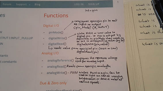
Thursday 17/03/16: Emma gave quite a clear lecture on digital Vs analog signals and went through the stages of communicating with the Fab device in the Arduino environment. She gave us some more information about input and output, but we will go through that in more detail in the future. What baffled me completely was that I was fully following (and enjoying) the lecture until it ended! From then on I was again completely lost.
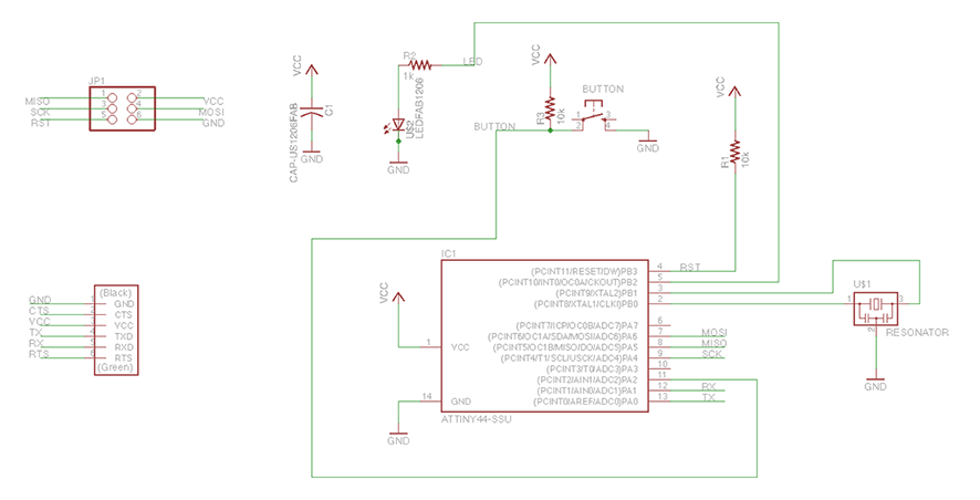
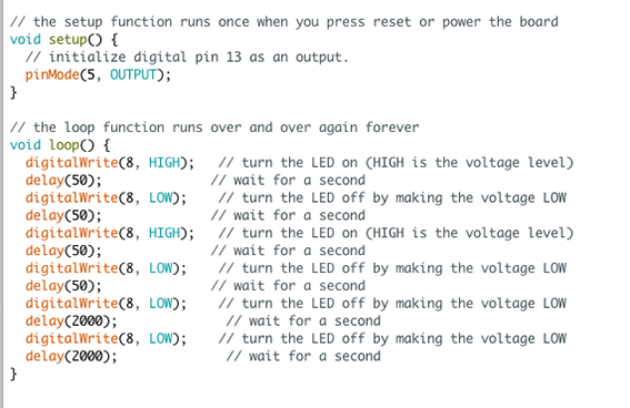
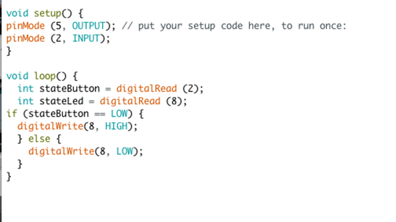
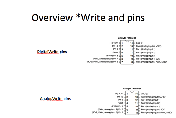
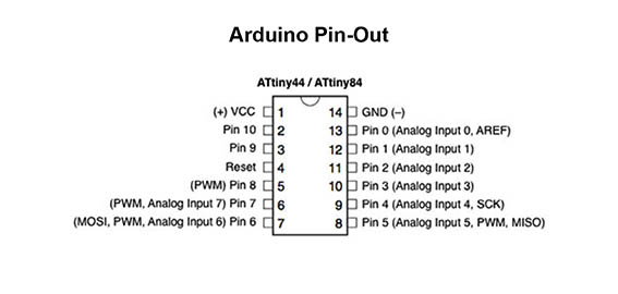
I stayed at the Fab Lab for most of the afternoon firstly to confirm that my Echo Hello boards were operable and ready to communicate with my computer. My second goal was to find where to begin so I could feel a little more confident about working alone over the weekend. Based on a given Arduino example, I attempted to get the LED to blink. I knew that there was nothing wrong with it because Emma had used it for the example in class. After some efforts, I realized that this was not going to happen so I called Emma who pointed out that the pin numbers in my code were wrong. This is because we are using the Arduino IDE to program a different PCB board with an ATTiny microcontroller, instead of an Arduino microcontroller. I returned to my schematic and spotted the correct number which was number 5. Then looked at the Arduino pinout to understand that it corresponded to pin number 8. I WRONGLY understood that I should set the ‘pinMode’ to 5 and ‘digitalWrite’ to 8 but I did finally see an extremely faint LED blinking (Please see Monday’s entry for the solution to the faint light). I played a little bit with the values to change the speed of the blinking which was successful so I only had two goals for the weekend. To program the push-button and to take a reading from the board.
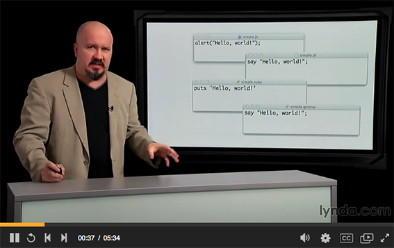
On Friday 18/03/16, I decided that it would be a good start to look at some of the previous years’ documentation to figure out where to start from. I then felt that I needed more solid foundations and began to watch a series of tutorials, the first four of them from ‘lynda.com’ to which I have access through work. I did not watch them all through to the end, but up to where I believed they were useful to me. You can find them here:
- Foundations of Programming: Fundamentals by Simon Allardice
- Up and Running with Arduino by Peggy Fisher
- Arduino Pulse Width Modulation by Rae Hoyt
- C Essential Training by Isac Artzi
- Secrets of Arduino
Most of them were very informative, but I still was not able to find the one suitable for me. They were either too detailed that made me disinterested or too advanced. The one with Peggy Fisher seemed to be doing the job, but at some point it jumped way ahead and got me lost.

I decided to make a potato and leek soup with yoghurt and parmesan cheese and to keep my hands occupied through the endless minutes or even hours of explicitly detailed tutorials. What worried me the most, was this statement by Isac Artzi: "More important than prior programming experience is a fundamental of mathematics and problem solving, of critical and analytical thinking. I'm guessing that you are already that type of person, since you're watching this course". I am not that kind of person. I am willing to explore, experiment and learn, but I believe there is something missing from the ‘tackling electronics’ equasion and I haven’t been able to spot it yet.
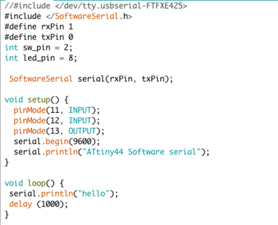
On Saturday 19/03/16, I had a plan. I was going to search for code written and explained in the same way as html in specific tutorials. Surely this must be simple to find… Following this tutorial gave me a faint blink on my small board, which made me quite happy and hopeful that I could continue by myself. (Find the link to the code file at the bottom of the page)

I proceeded to program the LED to turn on with the push of the button, but without any luck. I was following this tutorial. The fact that it was not working did not make any sense to me at all so I decided to try with my larger board and it worked! (Find the link to the code file at the bottom of the page)
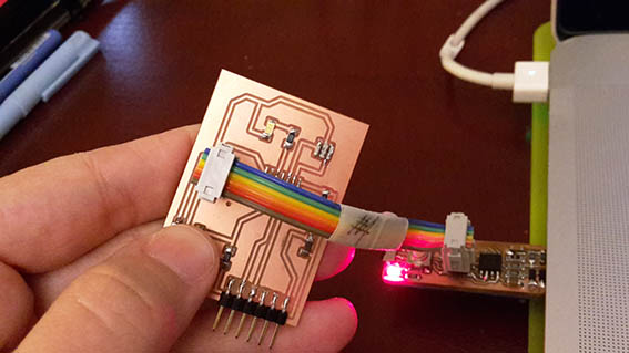
There must be something wrong with the path on my smaller board because two pins on the FTDI pin were shorted and I had to cut one off. I have a genuine question that I have not been able to find the answer to and that is why Eagle would suggest a specific route since it meant that it was creating a short. The fact is that I ran the ‘avrdude’ command on it and it said that it was ready to accept instructions. I suspect that the issue is between the FTDI pin and the push-button.
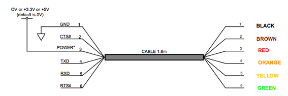
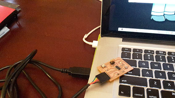
After successfully programming the LED and push-button, I attempted to get a reading from the board and I connected it to the FTDI cable (always connect the black wire to GND). That did not work and everything that started to fall into place became confusing again. Using the Arduino IDE is not very simple to me mostly because of the pin number issue. I am really getting frustrated with programming (and a little desperate, I must confess). Thankfully, I am sipping on a Gin and Tonic…
I decided that maybe I should try a proper programming language and I begun to read a little about "C" but have got nowhere yet. To this point I only have a confusing bundle of information in my head!
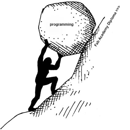
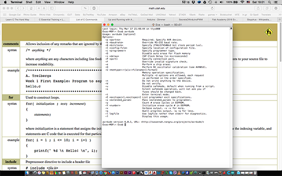
Right now, I feel like Sisyphus carrying a rock at the top of a hill, not quite sure if I will make it to the top before the rock rolls down again! (original image source) I hope that this is just a very steep learning curve, which I will eventually manage to climb. The plan tomorrow is to cover many pages of the ‘Atmel Data-Sheet’ hoping that it may help things fall into place.
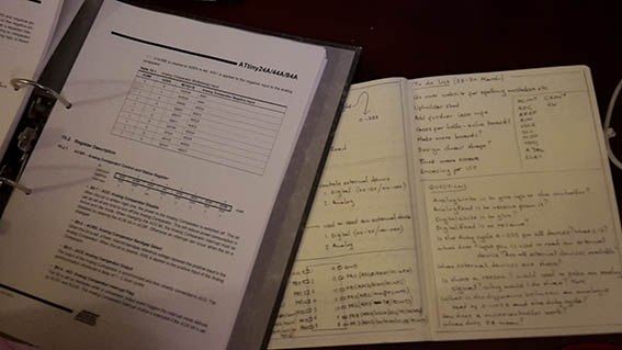
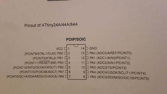
Sunday 20/03/16: I began to go through the data sheet and I started having a LOT of questions! Although the screen grab from Emma's presentation made things a little clearer, I soon felt that I needed to understand more about the abbreviations that I was reading. Especially those regarding the Attiny pin-out, so I wrote down its abbreviations and did some googling which gave me the following results:
-
PA (Port A) functions 0-7
- ADC (analog to digital converter - all PA pins): ADC input Channel
- AREF: External Analog Reference
- PCINT: Pin Change Interrupt
- AIN0: Analog Comparator (Positive Input)
- AIN1: Analog Comparator (Negative Input)
- T: Timer/Counter Clock Source
- USCK: USI Clock Three wire mode
- SCL: USI Clock Two wire mode
- DO: USI data Output (Three wire mode)
- DI: USI data Input (Three wire mode)
- MISO: SPI Master Data Input/ Slave data output
- MOSI: SPI Master Data Output/ Slave data Input
- OC: Timer/Counter (Compare Match)
- ICP: Timer Counter Input Capture Pin
-
PB (Port B) funtions 0-3
(All PB pins are 4bit input and output with internal pull up resistors and PB3 is used for Reset)
- PCINT: Pin Change Interrupt
- XTAL: Crystal Oscillator Input
- CLKI: External Clock Input
- INT: External Interrupt Input
- OC: Timer/Counter (Compare Match)
- CKOUT: System Clock Output
- RESET: Reset
- dW: Debug Wire
An electronic Oscillator is an electronic circuit that produces a periodic, oscillating electronic signal, often a sine wave or a square wave. Oscillators convert direct current (DC) from a power supply to an alternating current signal.
The CPU requires a fixed number of Clock ticks (or clock cycles) to execute each instruction. The faster the clock, the more instructions the CPU can execute per second. Clock speeds are expressed in megahertz (MHz) or gigahertz (GHz).
The Interrupts refer to a notification, communicated to the controller, by a hardware device or software, on receipt of which controller momentarily stops and responds to the interrupt. Whenever an interrupt occurs the controller completes the execution of the current instruction and starts the execution of an Interrupt Service Routine (ISR) or Interrupt Handler. ISR is a piece of code that tells the processor or controller what to do when the interrupt occurs. After the execution of ISR, controller returns back to the instruction it has jumped from (before the interrupt was received). The interrupts can be either hardware interrupts or software interrupts.
The Analog Comparator (AC) is a module that compares two analog input voltages and outputs a signal level indicating which of the inputs is greater or lesser. An analog comparator is basically an amplifier without feedback and thus has very high gain.
The Universal Serial Interface (USI) is a multi purpose hardware resource which provide the basics hardware for various serial communications and is faster and reliable than implementing it in software.
The Serial Peripheral Interface (SPI) bus is a synchronous serial communication interface specification used for short distance communication, primarily in embedded systems.
ASCII stands for American Standard Code for Information Interchange. Computers can only understand numbers, so an ASCII code is the numerical representation of a character such as 'a' or '@' or an action of some sort.
A potentiometer, informally a pot, is a three-terminal resistor with a sliding or rotating contact that forms an adjustable voltage divider. If only two terminals are used, one end and the wiper, it acts as a variable resistor or rheostat.
In electronics, a digital-to-analog converter (DAC, D/A, D-A, D2A, or D-to-A) is a function that converts digital data (usually binary) into an analog signal (current, voltage, or electric charge). An analog-to-digital converter (ADC) performs the reverse function.
A processor Register is a quickly accessible location that is available to a digital processor’s central processing unit (CPU). Registers usually consist of a small amount of fast storage, but some have specific hardware functions, and may be read-only or write-only.
Debugging is the process of finding and resolving bugs or defects that prevent correct operation of computer software or a system.
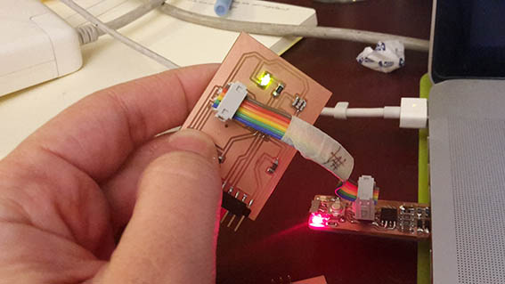
On Monday 21/03/16: in the Fab Lab I tried to put my toughts in order and I asked Emma a bunch of questions that made things a lot clearer for me. I also saw that my colleague Marije had a much brighter green LED so I tried to solve this issue. I changed my resistor from a 10K Ohm to a 499 Ohm but I had no luck with that and then I also replaced the LED. The result was the same until Emma had a look at my code. I was assigning ‘pinMode’ to 5 and ‘digitalWrite’ to 8 because I thought that this was what I should do regarding the Arduino Programming environment in conjuction with the ATtiny microcontroller. What I should have done was merely to figure out which pin corresponds to the Arduino microcontroller and always use that number. I did this minor correction and I got a bright green LED. It is amazing how electronics can sometimes work even with the wrong settings! Emma also deleted a lot of unecessary coding entries that I had in my document.
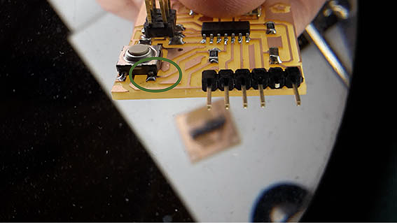
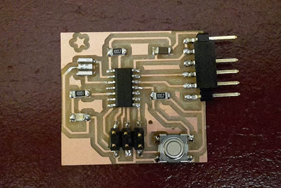
I then proceeded to debug my smaller PCB board which had communication issues with the button. Today I learned that debugging as a term can be used for hardware issues as well. I looked at my schematic and my board and consulted with Emma to come to the conclusion that the circuit was fine (despite the already spotted issue of the short between the two pins). Upon careful inspection, once again we had a revelation. One corner of the button was not soldered… I added some solder to it and I happily saw the LED coming on at the push of the button.
I then wanted to take a reading from the boards and I attempted this several times making some changes in the code while figuring it out. In the end I managed to get those readings from both boards but it seems that my code still had a lot of unecessary information which Emma needed to delete!
I then attempted to make the LED fade in at the push of the button and I tried this by having two IDE windows open and editing them in a third window. The first was one that simply turned on the LED by pushing the button and the second from a LED fade-in loop. I could not believe my eyes when I succeeded! But the video above is evidence of this!

To be honest, I do think that errors could be written in plainer English so that the average user can understand, but I am beginning to get a grip around this. I am still however reading and waiting for the ‘magic click’ that will make things fall into place. In any case I have decided to spend my time getting familiar with the Arduino IDE since it is something that I will be using in my final project, rather than spend too much time experimenting with other languages and environments. Emma walked me through the setup and very basic communication in "C" and "Python" but I do feel it is wiser to master one way of communication first before moving on to another.
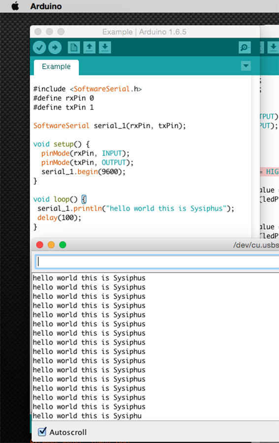
On Tuesday 21/03/16: I understood a lot more about the Arduino IDE in relation to how it can be configured to work through the Fab ISP. The most important thing being that if I want to get a serial reading from it I need to have the library installed, which is what ‘SoftwareSerial’ stood for! And it was the reason I could not follow the Arduino tutorials. From then on I even managed to program it to fade in at the push of a button without using any pre-given templates. (Find the link to the code file at the bottom of the page)
-
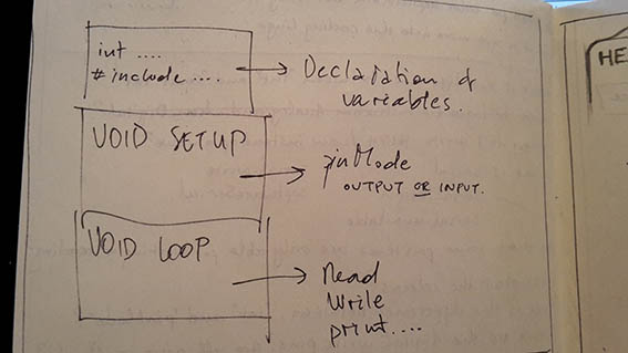
It was important to me to understand that the IDE is devided into three sections:
- The declaration of variables (where the I define the pins that I am going to use)
- The void setup (where I set up which specific pins will be input and which output)
- The void loop (Where I actually put the code of what I want my components to do)
As I begun to understand more, I got confused again by which component is digital and which is analog so I know which command to give it! Apparently a push-button is always a digital component so I need to use the digitalRead / digitalWrite commands. This to me is strange because if I am able to physically push it to change it’s status, then it is logical that it is an analog component. On the other hand, the LED can be either connected to a digital or an analog pin. At least I believe I have reached a point where I can search for questions on the internet and understand the answers! From this point onwards, it’s a matter of grasping the capabilities and to dare play with code and new components.
To sum up about this week, I really don't know why I needed to list all those abbreviations at the top of this page and I am not sure I was watching the right tutorials. Whatever the case, I have begun to have much more understanding about the Arduino IDE and I may be even reaching the top of the hill. I will continue to play around with it in the following days in an attempt to get a better grip of it. I have already milled a Fabduino which is ready for stuffing.
What is more important to me is that I regain my enthusiasm at the end of every week.
Blinking LED — File LED-On with Button Push — File Button Push LED Fade-In — File Hello World — File Embedded Programming Lecture Back to Weekly Assignments Home